When I build devices that connect over long distances with LoRaWAN, one of the first decisions I have to make is about speed versus battery life. In a previous project, I made a sensor that only checks in with the network a couple of times a day. This is called a Class A device, and it's fantastic for saving power and running for years on a battery. But the big tradeoff is that it only listens for commands for a very brief moment right after it sends its own data.
That's why for this project, I wanted to build something that responds to commands almost instantly. This is a Class C device, which means it's always listening. No matter when I send a command from my network server, the device hears it right away and acts on it. The downside is that it uses a lot more power because it's never sleeping, so it's not practical for a small battery. I usually power these kinds of projects from a wall outlet or a large battery pack.
In this article, I'm going to show you how I built this always-listening relay controller. I'll walk you through the simple wiring and the code that makes it work, so you can build a device that you can control in real-time from anywhere you have an internet connection.
This video is sponsored by Altium Develop.
Connecting the Hardware
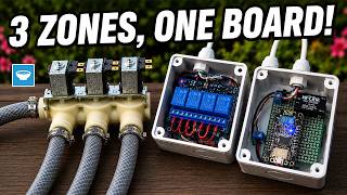
For this project, I'm using a Heltec LoRa 32 board, which has an ESP32 microcontroller and a LoRa radio all in one, which makes things very simple. To control actual devices like lights or motors, I connected it to a two-channel relay board. This relay board is like a remote-controlled switch that can handle much higher power than the microcontroller itself.
The wiring is very straightforward and only needs four wires. I take a 5V pin from the Heltec board and connect it to the relay module's VCC pin, and then I connect a GND pin from the board to the relay's GND. This provides the power the relays need to operate. To actually control the relays, I use two of the board's digital pins. I connected pin 47 to the input for the first relay channel, and pin 48 to the input for the second relay channel.
That's really all there is to the physical setup. With just these four connections, the microcontroller can now send signals to turn each relay on or off independently. The next step is to upload the code that will tell the board how to listen for commands over LoRa and use these pins to flip the relays.
The Code: Teaching the Device to Listen
The code for this project is based on an example from Heltec, which I modified for my specific needs. The first thing I do in the code is to define the crucial LoRaWAN network credentials, which are like the device's address and password to connect to The Things Network. I also set the device to operate in Class C mode right at the start, which is the line of code that tells it to stay awake and listen constantly for incoming messages.
Most of the magic happens in a special function I created that handles incoming messages. When a command is sent from the network server, this function is triggered automatically. The command is just two numbers. The first number tells the device what action to take, like turn on or turn off, and the second number tells it which relay to perform that action on. For example, if the code sees the numbers 01 and 01, it understands that means "turn on relay number one."
I also added a little extra logic for convenience, like a special command that turns both relays off at the same time. If the device receives a command it doesn't understand, it just prints an error message to the serial monitor so I can debug it. The rest of the setup code is standard, mostly just initializing the board and connecting it to the LoRaWAN network, so the device is ready to listen and act the moment it's powered on.
The code is available below.
/* Heltec V3 LoRaWAN Dual Relay Control
 *
 * Author: Bill Kolicoski
 * YouTube: http://youtube.com/@TasteTheCode
 *
 * Function:
 * Control two relays via LoRaWAN downlink commands from a network server (e.g., TTN).
 * The device operates in Class C mode for continuous listening capability.
 *
 * Commands (2 bytes hex - [ACTION][RELAY]):
 *  01 01 -> Turn ON Relay 1
 *  01 02 -> Turn ON Relay 2
 *  02 01 -> Turn OFF Relay 1
 *  02 02 -> Turn OFF Relay 2
 *  03 03 -> Turn OFF ALL Relays
 *
 * Hardware:
 * - Heltec WiFi LoRa 32 V3 board
 * - Relay 1 connected to GPIO48 (active LOW)
 * - Relay 2 connected to GPIO47 (active LOW)
 *
 * Description:
 * 1. Joins LoRaWAN network using OTAA (Over-The-Air Activation)
 * 2. Operates in Class C mode for continuous RX window availability
 * 3. Listens for 2-byte downlink commands to control relays
 * 4. Sends minimal periodic uplink (status heartbeat every 10 minutes)
 *
 * Modified from Heltec Automation example
 * */

#include "LoRaWan_APP.h"

// REPLACE WITH KEYS FROM YOUR TTN CONSOLE
/* OTAA para TTN */
uint8_t devEui[] = { 0x00, 0x00, 0x00, 0x00, 0x00, 0x00, 0x00, 0x00 };
uint8_t appEui[] = { 0x00, 0x00, 0x00, 0x00, 0x00, 0x00, 0x00, 0x00 };
uint8_t appKey[] = { 0x00, 0x00, 0x00, 0x00, 0x00, 0x00, 0x00, 0x00, 0x00, 0x00, 0x00, 0x00, 0x00, 0x00, 0x00, 0x00 };

/* ABP para TTN */
uint8_t nwkSKey[] = { 0x00, 0x00, 0x00, 0x00, 0x00, 0x00, 0x00, 0x00, 0x00, 0x00, 0x00, 0x00, 0x00, 0x00, 0x00, 0x00 };
uint8_t appSKey[] = { 0x00, 0x00, 0x00, 0x00, 0x00, 0x00, 0x00, 0x00, 0x00, 0x00, 0x00, 0x00, 0x00, 0x00, 0x00, 0x00 };
uint32_t devAddr = ( uint32_t )0x00000000;

/*LoraWan channelsmask, default channels 0-7*/
uint16_t userChannelsMask[6]={ 0x00FF,0x0000,0x0000,0x0000,0x0000,0x0000 };

/*LoraWan region, select in arduino IDE tools*/
LoRaMacRegion_t loraWanRegion = ACTIVE_REGION;

/*LoraWan Class, Class A and Class C are supported*/
DeviceClass_t loraWanClass = CLASS_C; // Changed to CLASS_C for continuous listening

/*the application data transmission duty cycle. value in [ms].*/
uint32_t appTxDutyCycle = 600000; // Increased to 10 minutes (only for initial join confirmation)

/*OTAA or ABP*/
bool overTheAirActivation = true;

/*ADR enable*/
bool loraWanAdr = true;

/* Indicates if the node is sending confirmed or unconfirmed messages */
bool isTxConfirmed = false; // Changed to false since we're not sending regular data

/* Application port */
uint8_t appPort = 2;
/*!
* Number of trials to transmit the frame, if the LoRaMAC layer did not
* receive an acknowledgment. The MAC performs a datarate adaptation,
* according to the LoRaWAN Specification V1.0.2, chapter 18.4, according
* to the following table:
*
* Transmission nb | Data Rate
* ----------------|-----------
* 1 (first)    | DR
* 2        | DR
* 3        | max(DR-1,0)
* 4        | max(DR-1,0)
* 5        | max(DR-2,0)
* 6        | max(DR-2,0)
* 7        | max(DR-3,0)
* 8        | max(DR-3,0)
*
* Note, that if NbTrials is set to 1 or 2, the MAC will not decrease
* the datarate, in case the LoRaMAC layer did not receive an acknowledgment
*/
uint8_t confirmedNbTrials = 4;

// Relay pin definitions for Heltec V3
#define RELAY1_PIN 48   // GPIO pin for relay 1 control (change if needed)
#define RELAY2_PIN 47   // GPIO pin for relay 2 control (change if needed)

// Command structure: [ACTION][RELAY]
// Actions: 0x01 = ON, 0x02 = OFF, 0x03 = OFF ALL
// Relays: 0x01 = Relay1, 0x02 = Relay2, 0x03 = Both

/* Prepares the payload of the frame */
static void prepareTxFrame( uint8_t port )
{
 // Minimal payload - only send status update if needed
 // This is kept minimal since we're primarily a receiver
 appDataSize = 1;
 appData[0] = 0x00; // Status: listening
}

//downlink data handle function - Relay control based on received commands
void downLinkDataHandle(McpsIndication_t *mcpsIndication)
{
 Serial.println();
 Serial.println("========== DOWNLINK RECEIVED ==========");
 Serial.printf("+REV DATA:%s,RXSIZE %d,PORT %d\r\n",mcpsIndication->RxSlot?"RXWIN2":"RXWIN1",mcpsIndication->BufferSize,mcpsIndication->Port);
 Serial.print("+REV DATA:");
 for(uint8_t i=0;i<mcpsIndication->BufferSize;i++)
 {
  Serial.printf("%02X ",mcpsIndication->Buffer[i]);
 }
 Serial.println();
 Serial.println("======================================");

 // Check if we received exactly 2 bytes
 if(mcpsIndication->BufferSize == 2)
 {
  uint8_t action = mcpsIndication->Buffer[0];
  uint8_t relay = mcpsIndication->Buffer[1];

  // Handle commands
  if(action == 0x01) // Turn ON
  {
   if(relay == 0x01) // Relay 1 ON
   {
    digitalWrite(RELAY1_PIN, LOW); // Active low
    Serial.println("Command: RELAY 1 turned ON");
   }
   else if(relay == 0x02) // Relay 2 ON
   {
    digitalWrite(RELAY2_PIN, LOW); // Active low
    Serial.println("Command: RELAY 2 turned ON");
   }
   else
   {
    Serial.println("Error: Invalid relay number for ON command");
   }
  }
  else if(action == 0x02) // Turn OFF
  {
   if(relay == 0x01) // Relay 1 OFF
   {
    digitalWrite(RELAY1_PIN, HIGH); // Active low
    Serial.println("Command: RELAY 1 turned OFF");
   }
   else if(relay == 0x02) // Relay 2 OFF
   {
    digitalWrite(RELAY2_PIN, HIGH); // Active low
    Serial.println("Command: RELAY 2 turned OFF");
   }
   else
   {
    Serial.println("Error: Invalid relay number for OFF command");
   }
  }
  else if(action == 0x03 && relay == 0x03) // Turn OFF ALL
  {
   digitalWrite(RELAY1_PIN, HIGH); // Active low - OFF
   digitalWrite(RELAY2_PIN, HIGH); // Active low - OFF
   Serial.println("Command: ALL RELAYS turned OFF");
  }
  else
  {
   Serial.printf("Unknown command: %02X %02X\r\n", action, relay);
  }
 }
 else
 {
  Serial.printf("Invalid command size: %d bytes (expected 2)\r\n", mcpsIndication->BufferSize);
 }
}

void setup() {
 Serial.begin(115200);
 Mcu.begin(HELTEC_BOARD,SLOW_CLK_TPYE);

 // Initialize Relay pins (Active LOW)
 pinMode(RELAY1_PIN, OUTPUT);
 digitalWrite(RELAY1_PIN, HIGH); // Start with Relay 1 OFF (HIGH = OFF)

 pinMode(RELAY2_PIN, OUTPUT);
 digitalWrite(RELAY2_PIN, HIGH); // Start with Relay 2 OFF (HIGH = OFF)

 Serial.println("LoRaWAN Dual Relay Control - Listening Mode");
 Serial.println("Relay 1 Pin: GPIO" + String(RELAY1_PIN) + " (Active LOW)");
 Serial.println("Relay 2 Pin: GPIO" + String(RELAY2_PIN) + " (Active LOW)");
 Serial.println();
 Serial.println("Commands (2 bytes hex):");
 Serial.println(" 01 01 -> Turn ON Relay 1");
 Serial.println(" 01 02 -> Turn ON Relay 2");
 Serial.println(" 02 01 -> Turn OFF Relay 1");
 Serial.println(" 02 02 -> Turn OFF Relay 2");
 Serial.println(" 03 03 -> Turn OFF ALL Relays");
}

void loop()
{
 switch( deviceState )
 {
  case DEVICE_STATE_INIT:
  {
#if(LORAWAN_DEVEUI_AUTO)
   LoRaWAN.generateDeveuiByChipID();
#endif
   LoRaWAN.init(loraWanClass,loraWanRegion);
   //both set join DR and DR when ADR off
   LoRaWAN.setDefaultDR(3);
   break;
  }
  case DEVICE_STATE_JOIN:
  {
   LoRaWAN.join();
   break;
  }
  case DEVICE_STATE_SEND:
  {
   // Send minimal status update
   prepareTxFrame( appPort );
   LoRaWAN.send();
   deviceState = DEVICE_STATE_CYCLE;

   // Print Class C status
   Serial.println("Device in Class C mode - continuous RX enabled");
   Serial.println("Ready to receive downlink commands");
   break;
  }
  case DEVICE_STATE_CYCLE:
  {
   // Schedule next packet transmission
   txDutyCycleTime = appTxDutyCycle + randr( -APP_TX_DUTYCYCLE_RND, APP_TX_DUTYCYCLE_RND );
   LoRaWAN.cycle(txDutyCycleTime);
   deviceState = DEVICE_STATE_SLEEP;
   break;
  }
  case DEVICE_STATE_SLEEP:
  {
   // Switch to Class C after first uplink to enable continuous RX
   LoRaWAN.sleep(loraWanClass);
   break;
  }
  default:
  {
   deviceState = DEVICE_STATE_INIT;
   break;
  }
 }
}
How It Works
Once the device is powered on and connected to The Things Network, it just sits there listening. To test it, I go to the device's page on the network server console. There's a messaging section where I can type in a command and send it directly to the device. For instance, when I send the command "01 01", I can watch the first relay click on almost instantly. The command travels from my computer through the internet, to a LoRaWAN gateway, and then wirelessly to my device.
I have a few different commands set up. Sending "01 02" turns on the second relay, and "02 01" turns the first one off. If I want to turn everything off at once, I just send the command "03 03". The device receives this two-number code, my program deciphers it, and it changes the voltage on the digital pins connected to the relays, making them flip on or off accordingly.
This immediate response is the whole point of using a Class C device. There's no waiting for the device to wake up or send its own data first. The moment I hit the send button, the command is on its way, and the action happens a second later. It feels like having a real-time remote control that works over a very long range.
LoRaWAN Classes
To understand why this device responds so fast, it helps to know about the different LoRaWAN classes. Think of Class A as a device that's mostly asleep. It only wakes up to send a quick message and then immediately opens its "ears" for a very short reply window before going back to sleep. If a command arrives at any other time, the device misses it completely. This is great for battery life but very slow for receiving commands.
Class C, which I used for this relay project, is the opposite. It's like a device that's always awake with its ears open. After it sends a message, it goes right back into a constant listening mode. This means it can get a command from the network server at any moment, which is why my relay turns on almost the instant I send the command. The trade-off is that it uses much more power because it never sleeps.
There's also a middle ground called Class B. Devices using this class still wake up periodically at scheduled times to check for messages, not just after they send data. This creates a balance, offering more chances to receive a command than Class A while still saving some power compared to Class C. You choose the class based on whether your project needs to save power or needs to react quickly.
Conclusion and next steps
And that's how I built a device that can be controlled instantly from anywhere using LoRaWAN. By using a Class C setup, I've traded battery life for immediate responsiveness, which is perfect for applications where you need to take action in real time, like turning on a water pump or activating an alarm. The wiring was simple, and the code just listens for specific number commands to control the relays.
If you want to try this yourself, you can find the complete Arduino code above and links to all the parts below. I've shared everything so you can get started on your own version. You could easily expand this by adding more relays or connecting different kinds of sensors and actuators.
I hope this project gives you a clear idea of how to make your own always-listening LoRaWAN devices. If you try it out or have questions about other classes like Class B, let me know in the comments. For more projects like this, you can follow my channel, and I'll see you in the next one.
Tools and Materials
The links below are affiliate links. This means if you click through and make a purchase, I may earn a small commission at no extra cost to you. This is a simple way to support my work and helps me continue creating free content for you. Thanks for your support!
- ESP LoRa 32 (Heltec) - https://s.click.aliexpress.com/e/_c3ygzJYp
- Meshnology N30 ESP LoRa 32
- 5V dual-channel relay board - https://s.click.aliexpress.com/e/_c3hAHSxF
- Mini Breadboards - https://s.click.aliexpress.com/e/_c42YdNAd
- Jump Wires - https://s.click.aliexpress.com/e/_c4nGyrdT
- SX1262 LoRaWAN Module - https://s.click.aliexpress.com/e/_c4lKwcBb
- Bench Power Supply - https://s.click.aliexpress.com/e/_c3LAFpp7
- Multimeter - https://s.click.aliexpress.com/e/_c3G4uHON
- LoRaWAN Gateway - https://s.click.aliexpress.com/e/_c3V8iLTf