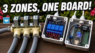
Last year I made and installed a DIY garden irrigation controller for my drip irrigation system and it worked wonders during the last growing season.
I had it set up through Home Assistant to turn on at night and water the garden so it stays fresh for the next day and so that the water has time to penetrate deeper before it is evaporated by the sun. That worked, there were times when the day was a touch cooler and there wasn't a need to be watered.
This brought the idea that I make a sensor to measure the soil moisture content and that I can then act on that with the watering, only turning it on if it is needed.

PCBWay offers services for custom PCBs, PCBA, 3D printing, CNC machining, Injection molding, and more.
Check out their shared projects section to explore ideas for your next project or order any of the already created PCBs from tousands of creators!
Parts and Materials
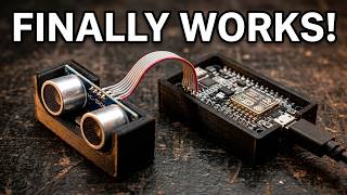
The star of the project is the capacitive soil moisture sensor that I covered in a previous video that is controlled by an ESP8266 ESP-07 module. The module will be flashed with the ESPhome firmware so we can connect it to Home Assistant and get the measurements in to control the irrigation.
I'll be using an ESP8266 ESP-07 module for two reasons. First, I already had this module at home, and second, since the project will be running on batteries, the module does not have any of the other components from the NodeMCU that I normally use so in theory it should use a bit less current as well.
To power everything, I'll be using two 18650 batteries wired in parallel, that I salvaged from a laptop battery.
ESP8266 ESP-07 Module Overview
The ESP-07 module has a ceramic antenna on board and a connector for an external antenna. It does not have any other peripherals, so it is very small and suitable for embedding into projects where size is a constraint.
Based on its datasheet. the module can operate from 3V up to 3.6V, it has one analog input that we will need for the capacitive soil moisture sensor that can accept up to 1V and a bunch of additional IO pins that we won't be using for now.
How to flash the ESP-07 module
To flash the module with the firmware, we need a USB to Serial adapter that can work with 3.3V. The VCC pin from the adapter needs to be connected to the VCC on the module as well as on the EN (enable) pin.
GND is connected to GND, but GPIO15 also needs to be connected to GND.
Finally, on power-up, GPIO0 needs to be connected to GND, so that the module can boot in flashing mode.
The data pins from the serial adapter, need to be connected to the serial pins on the ESP8266 module, but keep in mind that TX needs to connect to RX and RX needs to connect to TX for the communication to work.
I initially used the Arduino IDE to flash the Blink sketch and make sure that the communication could be established before I generated a bin file from ESPHome and uploaded it to the module with the help of the web installer of ESPHome.
Removing the power LED
Since I want to have as little power wasted in the project, I decided to remove the power indication LED from the ESP-07 module.
To do so, I used my hot air rework station to heat the board from the bottom, and using some tweezers, I carefully removed the LED, making sure not to touch and move any of the other components.
This is a tricky procedure, but if you are trying to replicate the project, you can instead use a different module, like the ESP-12E that does not have a power LED.
Connect the soil moisture sensor
The capacitive soil moisture sensor outputs an analog signal that we need to feed into the ADC pin of the ESP-07 modules. Since the module is bare, the allowed input on its analog pin is between 0 and 1V so we need to create a voltage divider before we connect the sensor.
I created the divider with one 220kOhm and one 100kOhm resistor. They are wired in series and the output of the sensor is connected to the other lead of the 220k resistor. The second lead of the 100k resistor is connected to ground and from the midpoint, I connected them to the ADC pin on the ESP8266. This divider ensures that we never go beyond 1V on the ESP-07 so we don't damage it.
Powering the sensor from batteries
The success of the project depends on it being able to operate on batteries since I'm not able to run a wire in my backyard to power it. Technically, I might be able to power it from an outlet, but I also wanted to see how a sensor like this can operate on batteries and figure out what the challenges will be for it.
For the batteries, I used 2 18650 cells that I salvaged from an old laptop battery. They are still wired in parallel as they were in the pack so I did not break that connection but I used the welded strips to solder on them instead of the batteries. To be able to charge the batteries when needed and also to add undervoltage protection, I used a TP4056 charging board that should turn off the device once the battery is empty.
To know when this has happened, it is best if we can also monitor the battery voltage with an additional analog pin but unfortunately, the ESP8266 has only one analog input so we can't at the moment. I'll try to figure out how we can implement this in a future version.
ESPHome Deep Sleep
With everything connected, the sensor was using about 75mA of current while operating. If we estimate that the 18650 cell capacity is 2000mAh each, we can say that our pack has a capacity of 4000mAh. With an average of 75mA spent, it will only last around 53 hours or just over two days.
I want to be able to use the sensor for longer than that so I implemented the deep sleep component of ESPhome. This component puts the ESP8266 module to sleep at certain intervals so that it can save power. In our case, the measured humidity does not change so quickly so we can safely use intervals of a few hours in sleep and only measure once every 2 or 3 hours.
Now, when the module is in deep sleep, the measured current is around 3.5mA which is a reduction of around 95% in used power while sleeping. We can do even better than that by also disconnecting the moisture sensor not to be powered while the ESP is in deep sleep but I will leave that for the next version of the sensor.
In deep sleep, our pack can now power the device for about 47 days so combined with the running current, I'm guessing that the sensor will need to be charged once every month and a half but we'll see how it goes.
Preparing the Enclosure
To build the enclosure, I used an electrical junction box as I did not have access to a 3D printer to create a dedicated enclosure. Since there are several types of boxes, the selection came to a box that does not have any openings on the side and that has a lid that goes over the box.
I mounted the sensor with epoxy in a sloth on the bottom and I'm hoping that this way, I can prevent moisture from entering the enclosure as the lip of the lid can prevent any ingress. Additionally, I will add a bead of hot glue on the lid so that it is protected while outside.
ESPHome Device Code
Below is the final code I used on the device for now. Depending on how it behaves, I might change this in the future.
deep_sleep:
  run_duration: 30s
  sleep_duration: 20min

sensor:
  - platform: adc
    pin: A0
    name: "Soil Moisture"
    update_interval: 1s
    unit_of_measurement: "%"
    filters:
    - median:
        window_size: 7
        send_every: 4
        send_first_at: 1
    - calibrate_linear:
        - 0.53 -> 100.00
        - 0.63 -> 0.00
    - lambda: if (x < 1) return 0; else return (x);
    accuracy_decimals: 0
Final assembly and testing
Once everything was ready and assembled, I let it run for a couple of days on my bench just to make sure that it operated as expected and that everything was OK before putting it outside. So far, it seems to operate smoothly so hopefully it will go in the garden very soon.
Since this is my first battery-operated sensor in Home Assistant, I expect that things will go wrong and that I will need to make some modifications down the line. If you are interested in seeing the progress on the sensor, then be sure to subscribe to my YT channel to get all the updates.
Below are all the tools and materials used in the project and by purchasing through them, you are supporting my channel with no extra cost for you.
- ESP8266 ESP07 Module - https://s.click.aliexpress.com/e/_onPzbBs
- Capacitive Soil Moisture Sensor - https://s.click.aliexpress.com/e/_m0WA2LU
- Sensor with ESP32 Module combo - https://s.click.aliexpress.com/e/_DmHGbxv
- USB to Serial adapter - https://s.click.aliexpress.com/e/_oCHEON0
- Jumper Wires - https://s.click.aliexpress.com/e/_mtHfcPy
- Mini Breadboards - https://s.click.aliexpress.com/e/_on0J3Z8
- Mini PC for Home Assistant - https://s.click.aliexpress.com/e/_okQPKRy
- Soldering Rework Station - https://s.click.aliexpress.com/e/_m00zmaw
- Multimeter - https://s.click.aliexpress.com/e/_m0CIYDY
- Wire Snips - https://s.click.aliexpress.com/e/_omwVb18
- ESD Safe Tweezers - https://s.click.aliexpress.com/e/_ol7L3Ma