My mom used to own this boombox and now it is mine. It is a SANKEI Studio mixer model TCR95 from the 80s, and while it looks incredible, it has two problems that need fixing. The first is that the function switch only works when you nudge it slightly, which means there is either a dirty or broken contact inside. The second is that sound only comes from the left speaker, with nothing at all from the right. Let us open it up and see what is going on.
This video is sponsored by Altium Develop. Get your free trial here.
What We Are Working With
The TCR95 is a classic 80s boombox with an integrated cassette deck, AM/FM radio, and a graphic equalizer. It can run off batteries, an external DC supply, or straight from the 220V mains. The function switch is a four-pole unit with four positions: off, tape, AM, and FM. The FM position is what normally drives sound to the speakers, and that is the one causing trouble. The graphic equalizer, volume, and balance controls are all potentiometer-based, which means they are another common source of trouble in gear this old.
Opening Up the Boombox
The first challenge is figuring out how to get inside. Eight screws on the back plus all the knobs on the front need to come off. Once that is done, the boombox splits into two halves. One side holds the cassette deck, the station tuning wheel, and the function switch. The other half holds the amplifier side with the speaker connections. I disconnected the ribbon connectors joining the two halves to separate them fully before starting work.
Before doing anything else, I made sure the power cable was unplugged. This boombox can pull power from three different sources and the last thing I needed was a surprise.
Visual Inspection and Cleaning
Inside, the boombox looked surprisingly decent for its age. Some dust and a few spiderwebs, but nothing alarming. I cleaned everything out before touching anything else. Once the inside was clear, I did a full visual inspection of the wiring on both halves. Everything looked intact, but I noticed one of the connectors came out far too easily when I removed it. It has a locking mechanism that should hold it firmly in place. That got me suspicious straight away.
Fixing the Function Switch
The function switch sits on a sub-board connected to the main chassis. I removed the whole board by undoing three screws, which gave me much better access to the solder pads underneath. The joints all looked visually okay, but I reflowed them all with my soldering iron anyway just to be thorough.
After resoldering, I poured some 96% isopropyl alcohol directly into the switch while working it back and forth between positions. The idea is to flush out any dirt that might be causing the intermittent contact. You could see some gunk washing out with the alcohol as it drained onto a paper towel underneath. I repeated the flush a couple of times and then dried everything out with a short pass of my hot air gun set to around 400 degrees, keeping it brief to avoid heating the plastic housing or any of the nearby capacitors.
Cleaning the Potentiometers
With the front panel off, I also cleaned all the potentiometers for the graphic equalizer, volume, and balance controls. The EQ pots are fully exposed so cleaning them with IPA was straightforward. For the volume and balance knobs I poured alcohol directly into each one and worked the controls back and forth to loosen any oxidation or dried grease inside. A short pass of hot air to dry them out and they were done.
While reassembling, I spotted something worth investigating: a cable running to the front panel had been pinched under a panel edge at some point. The cable itself looked okay visually, but given that the connector was already suspiciously loose, the pinching had probably stressed the wire over years of heat cycles until the connector eventually let go. I tested every wire in that loom before putting things back together. All of them checked out fine.
First Test
With things partially assembled, I ran a quick test. The function switch was now working properly across all positions, which was a good sign. The right speaker had also come back to life. Both channels were playing, and none of the controls were crackling. But the right side was noticeably quieter than the left, and there was some odd noise when adjusting the balance knob. Something was still not right.
Tracking Down the Balance Issue
I pulled the potentiometer board out again for a closer look. There was some slightly sloppy soldering around the balance pot, and one of the pads looked like it might have a hairline crack. I resoldered all three pins on the balance pot and touched up a few other joints on the nearby connector that did not look right.
When I reassembled and tested again, the right speaker had gone completely silent. Whatever I had done made things worse. That meant the issue was definitely on that board and not somewhere in the cabling.
Looking more carefully at the board, I found it. There was a solder bridge between two separate PCB tracks near the balance potentiometer. The bridge was connecting one of the audio signal tracks directly to ground, which was killing the right channel entirely. I have no idea if that bridge was there from the original factory soldering or appeared later, but it had to go either way.
I removed the solder bridge with my soldering iron, verified there were no other shorts between the surrounding pads, and checked continuity from the correct pins through to the right places on the board.
Final Test and Wrap-Up
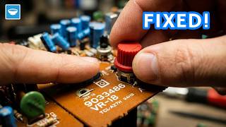
With everything reassembled and buttoned up, both channels are now working properly. The balance control sweeps cleanly from left to right with no crackling or noise. The function switch clicks between positions without any dead spots. FM radio, left channel, right channel, everything is behaving exactly as it should.
Conclusion
This repair turned out to be a combination of two separate problems. The function switch needed a proper clean with isopropyl alcohol to clear the intermittent contact. The right channel issue was caused by a solder bridge on the potentiometer board that was grounding one of the audio signal tracks. Once that bridge was found and removed, the right speaker came straight back.
The lesson here is to always check solder connections carefully before assuming a component is dead. A solder bridge can be almost invisible on a densely packed board, but its effect can look exactly like a failed part. Take your time, check the tracks, and verify continuity before you start swapping components.
If you enjoy repairs and builds like this, make sure to subscribe to my YouTube channel so you do not miss the next one.
Tools and Materials Used in the Video
- Soldering Station: https://s.click.aliexpress.com/e/_c4LJiGI3
- Soldering Kit: https://s.click.aliexpress.com/e/_c3StssI3
- Bench Power Supply: https://s.click.aliexpress.com/e/_c3X1M7SR
- Screwdriver Set: https://s.click.aliexpress.com/e/_c4MkK8wF
- Precision Screwdriver Set: https://s.click.aliexpress.com/e/_c3KRS94F
- Digital Multimeter: https://s.click.aliexpress.com/e/_c3Ko9U0f