For a while I have been collecting disposable vape devices because they almost always have a usable rechargeable lithium cell inside. I have been repurposing those cells in small electronics projects whenever I need a compact battery to keep something running for a while. Up until recently I had only come across two battery shapes inside these devices: flat cells and small cylindrical ones. Then I found a different type that was noticeably larger than anything I had opened before, and it had a USB-C port on the end. That port told me something interesting was hiding inside, and I had to find out what.
Before I get into the teardown, a quick mention of today's sponsor, PCBWay. If you are a maker building any type of electronics project, PCBWay makes the whole process straightforward. You upload your design files, choose your specs, and get high quality PCBs shipped to your door. They also offer CNC machining, 3D printing, and full PCB assembly, so you can go from prototype to finished product in one place. Pricing is very affordable for small runs and the turnaround is fast. Check them out here for a small welcoming bonus to get started.
What We Are Working With
The device I had picked up was larger than the ones I usually find, with a twist valve at the top end and a USB-C port at the bottom. The outer shell looked like a single piece of plastic, which meant everything inside had probably been loaded from the top during manufacturing.
Before cracking it open, I wanted to confirm it was still functional. I blew some air through the back end and it produced output, so it was clearly still working. I then plugged in a USB cable and a small screen on the device lit up, showing a charging indicator and a live battery percentage reading. That was a genuine surprise. I had not expected a disposable vape device to have a proper display on it. The screen showed the battery at about 10%, which was a safe level to work with during disassembly. Once I had confirmed the charging circuitry was live, I stopped charging and got ready to open it up.
Disassembling the Device
I grabbed a pair of pliers and some paper towels, since this kind of teardown can get messy. The top end of the device came apart first. Under the cover I found a silicon washer, followed by a sponge-like reservoir for holding liquid. Once those were out, I could see the heating element sitting down inside the tube.
Getting the main body open took a bit more work. The device turned out to be two sections: an aluminum upper tube and a plastic lower housing. I removed a sticker that was hiding the join between the two sections, then used vice grips to pull them apart. Once the bottom separated from the tube, I could see the battery sitting in the upper section and the PCB down in the plastic part below it.
As a safety measure before going further, I cut the wire connecting the battery to the heater element that I already removed. I did not want to accidentally short anything while probing around. After that I removed two screws securing the PCB, and from there everything started to slide out. Getting the board fully clear of the housing required some gentle pushing on the USB-C connector from the outside, but it came out cleanly without any damage.
Examining the PCB
The battery label was the first thing I checked. It is an 850mAh cell at 3.7 volts, giving 3.145 watt-hours. That is a step up from the 400mAh and 550mAh cells I had found in smaller devices before. Still compact, but genuinely useful for powering something small over a reasonable period of time.
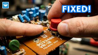
The PCB itself was more interesting than I expected, and the standout feature is the screen. It is a small dedicated display that shows battery percentage and a charging indicator symbol — the kind of thing you would normally have to source separately, wire up yourself, and write firmware for. On the side of the display there is a second indicator that appears to track the remaining liquid level, though I suspect it is calculated from usage time rather than directly measured. The board is marked as revision 1.3 and was manufactured on September 17, 2025.
What makes the screen especially interesting from a reuse perspective is the communication interface. It runs on four data pins labeled D2, D3, D4, and D5, alongside separate lines for VCC, ground, data, and clock. That layout points strongly to I2C or SPI. In theory, if you could reverse-engineer the protocol, you might be able to drive this display from your own microcontroller. At minimum, you get it working as-is by keeping the original PCB in the loop.
Microscope Inspection
I placed the board under a microscope to try to read the chip markings. The main microcontroller is labeled FZ80853508. Searching for it returned nothing, which suggests it is a proprietary chip produced for a specific manufacturer and not publicly documented. There is also a second chip nearby, labeled BC1500, which appears to sit close to the battery management section of the board. That one came up empty too.
One component I did manage to confirm was a P-channel power MOSFET. That makes sense: the circuit needs something to switch the current flowing to the heating element, and a MOSFET is the right choice for that job. The blue wire from the heater connected directly to it. There is also a component labeled as a microphone on the board, but in these circuits that part is typically being used as a pressure sensor. It detects when air is being drawn through the device, which is what triggers the heater to activate.
Testing Out of the Enclosure
Once I had the PCB fully out, I plugged the USB-C port into a cable to see if everything still worked. The display lit up, the charging indicator appeared, and the battery started charging normally. The entire system, the battery, the charging circuit, and the display, works perfectly outside of the original enclosure.
Conclusion
Taking this vape device apart gave me three things I can actually use in a future project. Most notably, there is a small display with a built-in battery percentage indicator and charging symbol, something you would normally have to source and integrate separately. There is a working USB-C charging circuit with no extra work required. And there is an 850mAh lithium cell that would otherwise have ended up in the bin. The proprietary microcontroller means I cannot reprogram anything on the board, but I can use the PCB as-is to charge the battery via USB-C, with the screen showing me the charge state as it goes. The P-channel MOSFET could probably be controlled if we try and poke around the PCB for a while but that is a topic for another time.
If you have ideas for what kind of project this battery and charging board could go into, drop a comment below. And if you want to catch more teardowns and builds like this one, make sure to subscribe to the Taste The Code YouTube channel so you do not miss the next one.