In a previous video, I built a power switch that let me control 12V sensors from a 3.3V GPIO pin on an ESP32. The idea was simple: when the device goes into deep sleep, cut the power to the sensors so we're not draining the battery. It worked, but a problem crept up once I connected it to a solar charging controller.
The solar controller has an MPPT function and charges a 12V lead acid battery from a solar panel. The way it constantly adjusts power creates a lot of electrical noise, and that noise was interfering with the transistor in my power switch, partially keeping the circuit open when it should have been closed. I tried adding several capacitors to filter it out, but my knowledge of signal filtering just isn't deep enough to nail that reliably.
So I took a different approach and built a prototype using an optocoupler instead of a transistor. An optocoupler completely isolates the two sides of a circuit electrically, which kills the noise problem at the source. And since I knew I'd need several of these controllers for upcoming client builds, I went ahead and designed a proper PCB for it. Those boards were manufactured by PCBWay, who are the sponsor of this video. They make it easy to go from a design file to real boards fast, and they handle everything from quick prototypes to complex multi-layer boards with full testing and quality checks.

What We Are Building
The new board shares almost exactly the same footprint as the original transistor-based power switch. The MOSFET and all the connectors are in the same positions, since that part of the design was already working fine.
The key difference is on the control side. Instead of a transistor, there's now a footprint for an optocoupler and a resistor sized to drive the optocoupler's LED from a 3.3V input. On the back of the board, all the connections are made through the PCB traces directly. No more manual wiring and solder bridges. This makes the build much faster and far cleaner.
Building the Board
The build starts with the two resistors. The first is R1, a 10K pull-up resistor on the MOSFET gate. I bend the leads slightly so it sits in the footprint without falling off before I get to the soldering iron. The second is a 100 ohm resistor for the optocoupler's LED drive circuit. This value works well at 3.3V, but you can adjust it to suit a different control voltage. Both get their leads bent outward after placing, then soldered in.
Next up is the optocoupler. The footprint has a square pad at pin 1 to show the correct orientation, and the chip itself has a dot on the same corner, so it's straightforward to line up. I place it in the footprint, tack one pin with a small amount of solder to hold it in place, then solder the remaining pins properly.
With the optocoupler done, the MOSFET goes in next. It sits in the same position as the previous board design, so nothing new here. Just place it and solder.
The last step is the screw terminal blocks for the wire connections. One lesson from this build: solder the terminals before the MOSFET in future. The MOSFET adds height to the board, which makes it hard to keep it lying flat on the bench. For now, I work one side at a time, soldering just one pin first to tack the terminal in place, then checking that it's sitting flat against the PCB. If it's not fully flush, I heat that first pin again and press it down before soldering the remaining pins. Getting this flat matters for both appearance and reliable connections.
The two output terminals have a slot on one end that lets you click them together into a wider block. I join them to make a four-channel block before soldering them down.
In just a few minutes, a board that used to take half an hour to hand-wire is done. That's the real payoff from designing a custom PCB. If you're building the same circuit more than once, it's absolutely worth investing the time to lay it out properly.
Testing It Out
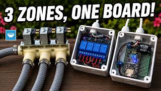
To verify the board works, I set up a test rig with an ESP32 that has a GSM module for remote control via SIM card. The ESP32 drives the power controller from GPIO41. On the output side, I'm powering an RS485 temperature and humidity sensor, and I've added a light on the output so there's something visible to confirm when the MOSFET switches. The 12V for the output side comes from a bench power supply, kept separate from the control circuit.
When I plug in the controller, the script starts immediately. The light turns on, the sensor powers up, the ESP32 reads the temperature and humidity data, then cuts the power to everything and sends the data before going into deep sleep for about a minute. After the sleep cycle, it wakes up, powers the sensor again, takes another reading, and the cycle repeats.
The board works, the PCB layout is correct, and the optical isolation is doing its job.
Conclusion
Swapping the transistor for an optocoupler solved the electrical noise problem and gave full isolation between the 3.3V control side and the 12V output side. Designing a custom PCB made the build repeatable and fast. If you find yourself building the same circuit more than once for a project or a client, take the time to design a PCB for it. The time you save on every subsequent build more than pays for the design effort upfront.
If you found this article and video interesting, make sure to subscribe to my YouTube channel so you do not miss any of the upcoming videos.
Links & Resources
- PC816 Optocoupler: https://s.click.aliexpress.com/e/_c4LAcaZV
- MOSFET: https://s.click.aliexpress.com/e/_c3FWXQ0x
- Assorted Resistors: https://s.click.aliexpress.com/e/_c35H89WT
- Screw Terminal Blocks: https://s.click.aliexpress.com/e/_c3dY1Nj5
- UART to RS485 Converter: https://s.click.aliexpress.com/e/_c4NrnAOX
- SDLA12TA Solar Charging Controller (MPPT): https://s.click.aliexpress.com/e/_c3dEK2zz
- RS485 Temperature and Humidity Sensor: https://s.click.aliexpress.com/e/_c3c5CmUL
- Waveshare A7670 ESP32 Controller: https://s.click.aliexpress.com/e/_c41T6teT
- Soldering Station: https://s.click.aliexpress.com/e/_c4OSNA8j
- Bench Power Supply: https://s.click.aliexpress.com/e/_c3MKBTbN
- Digital Multimeter: https://s.click.aliexpress.com/e/_c3kCZydl