In this article, we will look into the basics of switches and how we can use switches with an Arduino microcontroller in our projects. Stick to the very end to learn about a few tips and tricks when connecting them.
Momentary vs. Latching Switches
In electronics, a switch is a device that can connect or disconnect two points (or more commonly known as poles) in an electrical circuit. Based on the principle of operations, there can be multiple types of switches but the basic two are a momentary switch and a latching switch.
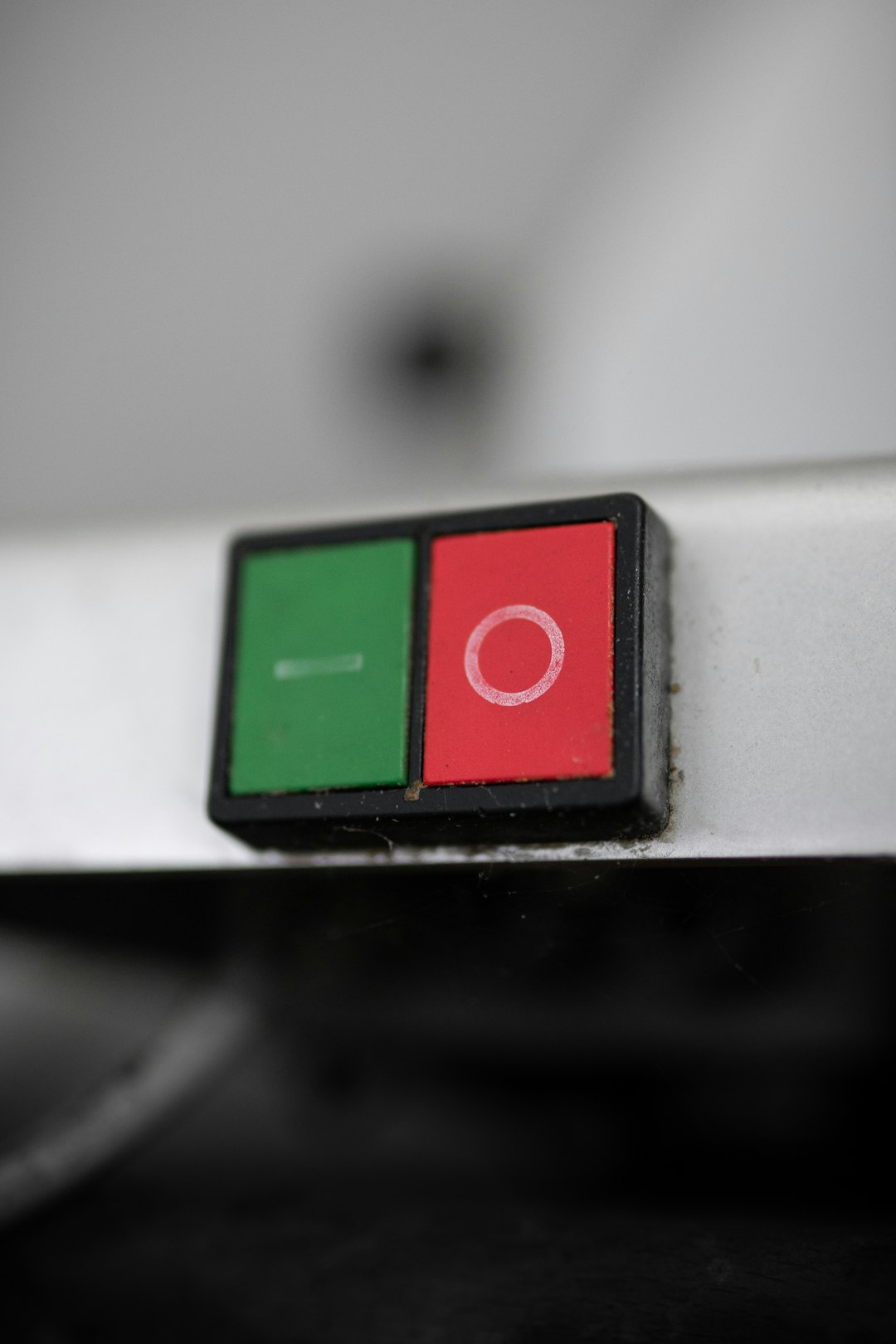
With momentary switches, the connection points are connected while an external force is applied to the switch, and that state is immediately reversed once the external force is stopped.
A latching switch on the other side requires an external force to change its state but it will then keep that state indefinitely until the same force is applied again to change its state. For latching switches, we need to act twice on them so they can be brought back to their initial state while momentary switches return to their initial state automatically once the applied external force is removed.
Different types of mechanical switches
A mechanical switch can come in virtually unlimited sizes and shapes depending on its required application. They can vary from being extremely tiny to enormous but in reality, their principle of operation is always the same. They can either connect or disconnect two or more points in a circuit when force is applied to them.
Depending on the type of engagement and the physical appearance of the switch, we can separate them in several different basic styles.
Rocker Switch
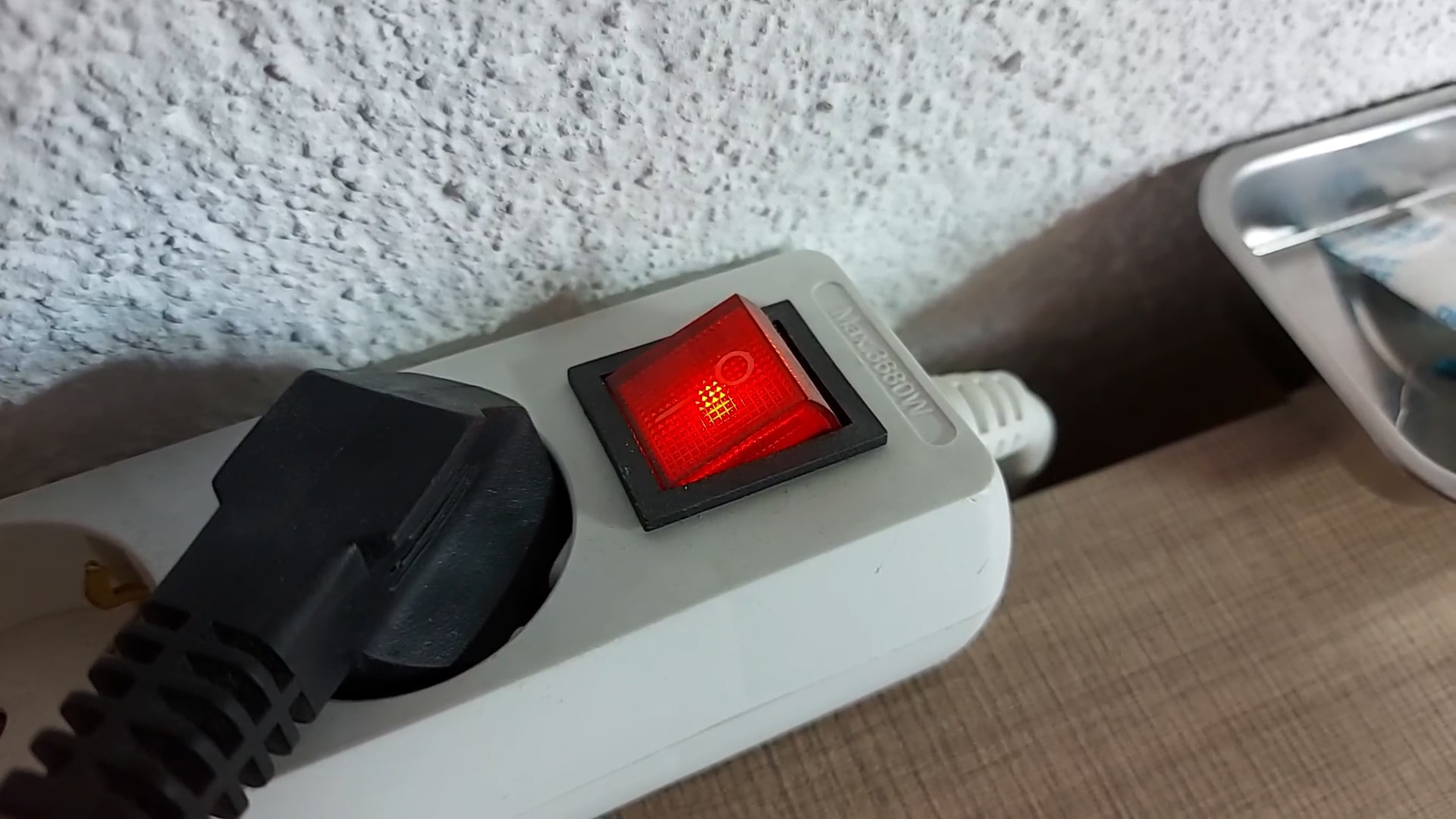
Rocker Switch
A rocker switch is typically used to control household lights, control power strips, computer power supplies and many other typically smaller devices. The rocker of the switch is balanced in the middle and can tilt to either side to turn ON or OFF.
These switches usually have mounting clips built on their case so they are perfect for use with DIY projects where they can be pushed into an appropriate hole in the enclosure.
Toggle Switch
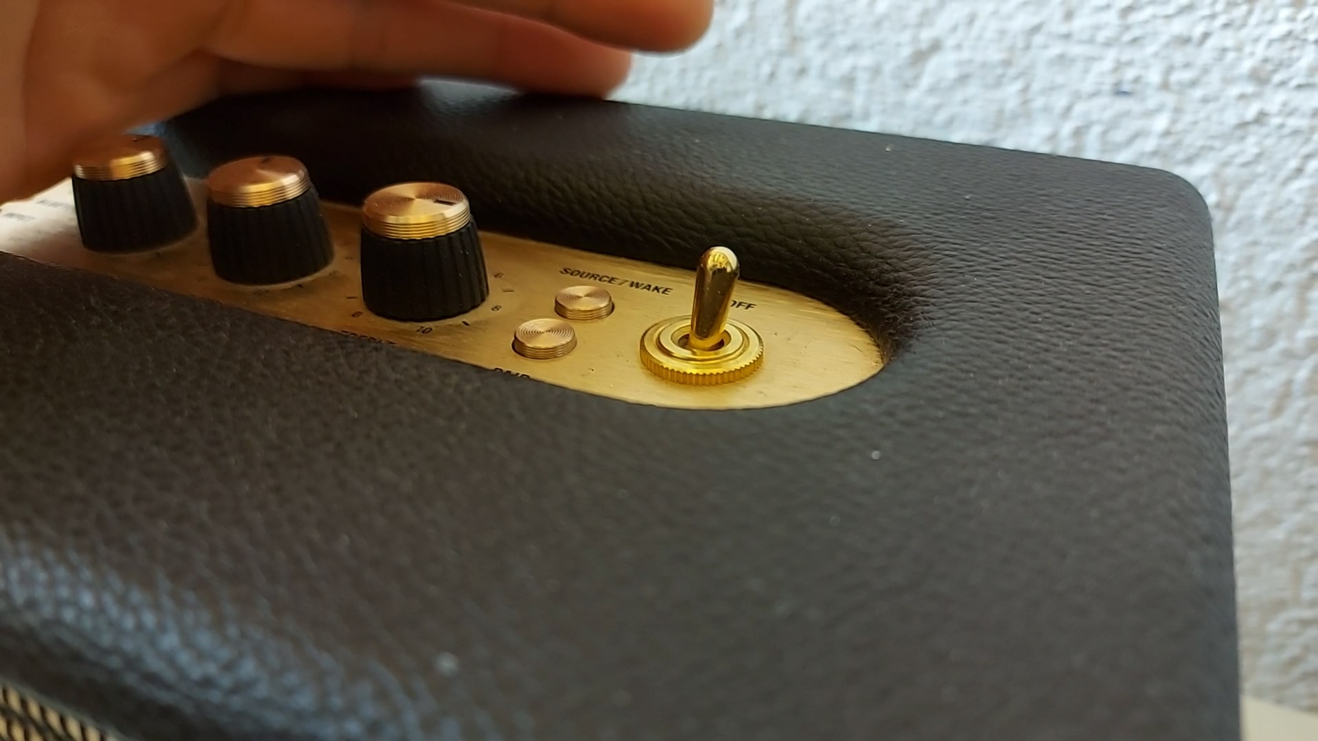
Toggle switch
Toggle switches are primarily used in electrical panels or in appliances where a more visual appeal is required. They have a lever that can be moved to the ON or OFF position and are usually mounted from the backside of the mounting panel with a holding screw on the top.
Slide Switch
Slide switch
Very often some small devices have slide switches built into them as they are very small and handy to be actuated with just one finger while holding the device. These slide switches are controlled by sliding the control surface from one end to the other and are also very useful as state or selection choosing switches in devices.
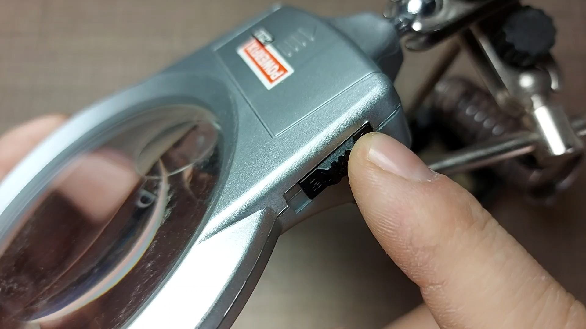
DIP Switch

A special type of switch based on multiple slide switches is the DIP switch or dual in-line package switch where multiple very small slide switches are placed one next to the other so a selection can be made in a circuit based on what switches are on or off.
This type of switch is very common in radio controlled devices where the working frequency and channel is selected with this kind of DIP switches.
Rotary Switch
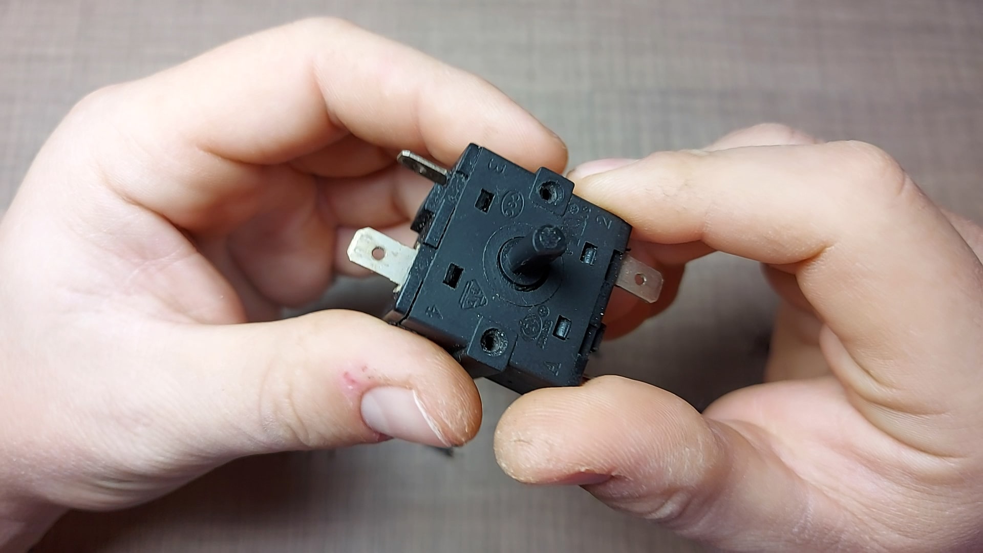
Rotary switch
When a switch is operated by rotation or turning, it is called a rotary switch. These are very often used in situations where more than two positions are needed or when a solid decisive action is needed to turn on a machine or higher load.
Push Button
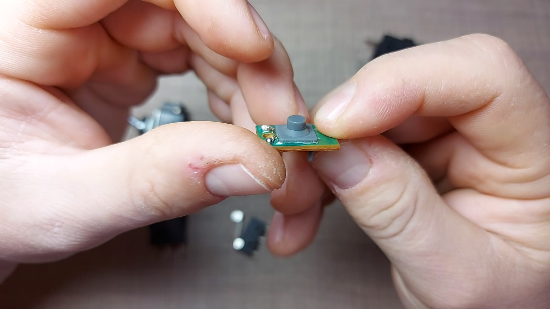
Push button
Probably the most common type of switch used in electronic devices is the humble push button that only connects the two poles of the switch when being pressed. Once the pressure is released, an internal spring or membrane separates the contacts and the connection is broken.
They come in many shapes and sizes depending on the application as limit switches, input switches, keypads, reset switches, and general-purpose interaction switches. The majority of them need to be mounted to a circuit board of some sort but there are also some that can be panel mounted.
Other switches
The list can literally go on forever as there are a ton of other types of switches, like this pressure operated switch, but their principle of operation is still the same.
Poles and throws
Now that we've seen some of the basic types of switches based on their appearance and type of operation, there is one more property of a switch that we need to be aware of.
When a switch is actuated, the basic operation is that it connects one input pole to one output saying that it has a single throw. A single "Pole" indicates that the switch can control a single circuit while the "throw' indicates the number of contacts that that pole can connect to.
A typical changeover contact that switches between two positions is said to have a double-throw where a single input pole can be connected to two output poles so this switch can be labeled as single pole, double throw, or SPDT for short.
A DPST switch or double pole, single throw switch, on the other hand, has two input and two output poles that are not connected to each other. This switch can turn ON or OFF two independent circuits with a single press.
Multiple combinations of poles and throws can be made in a single switch to create a switch that is built for a specific need and activates multiple circuits with a single operation.
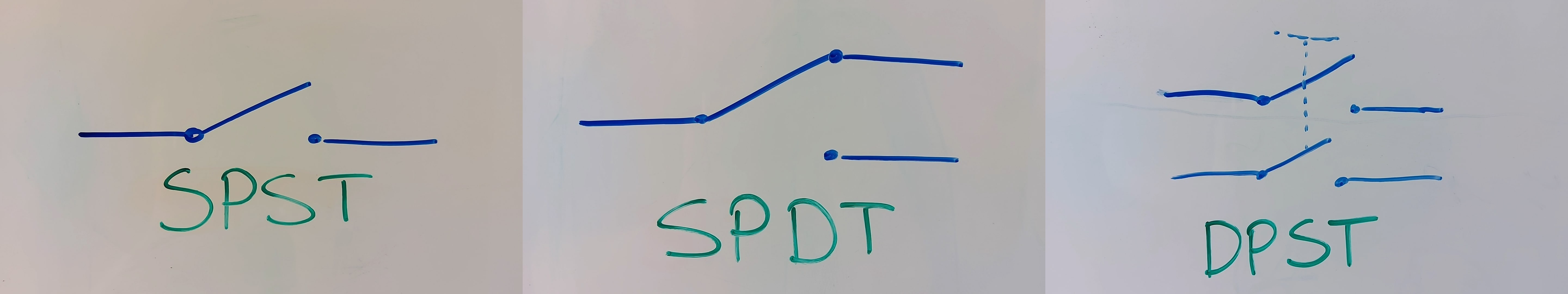
SPST, SPDT, and DPST symbols
These videos take up a lot of my free time. To help me continue making these videos, head out to Patreon where you can support the channel for as low as $1.
All of the Patreon funds will be directly used for the channel, either for parts for projects or for tools and equipment and I'm thankful to all of you in advance for helping out.
Use of switches with Arduino
Now, that we know a lot about switches, let's see how we can use one or more in our Arduino projects.
To start, we will need a breadboard, an Arduino or any other compatible board of your choice, a switch, a resistor, and some jumper wires. Links to everything will be down in the description.
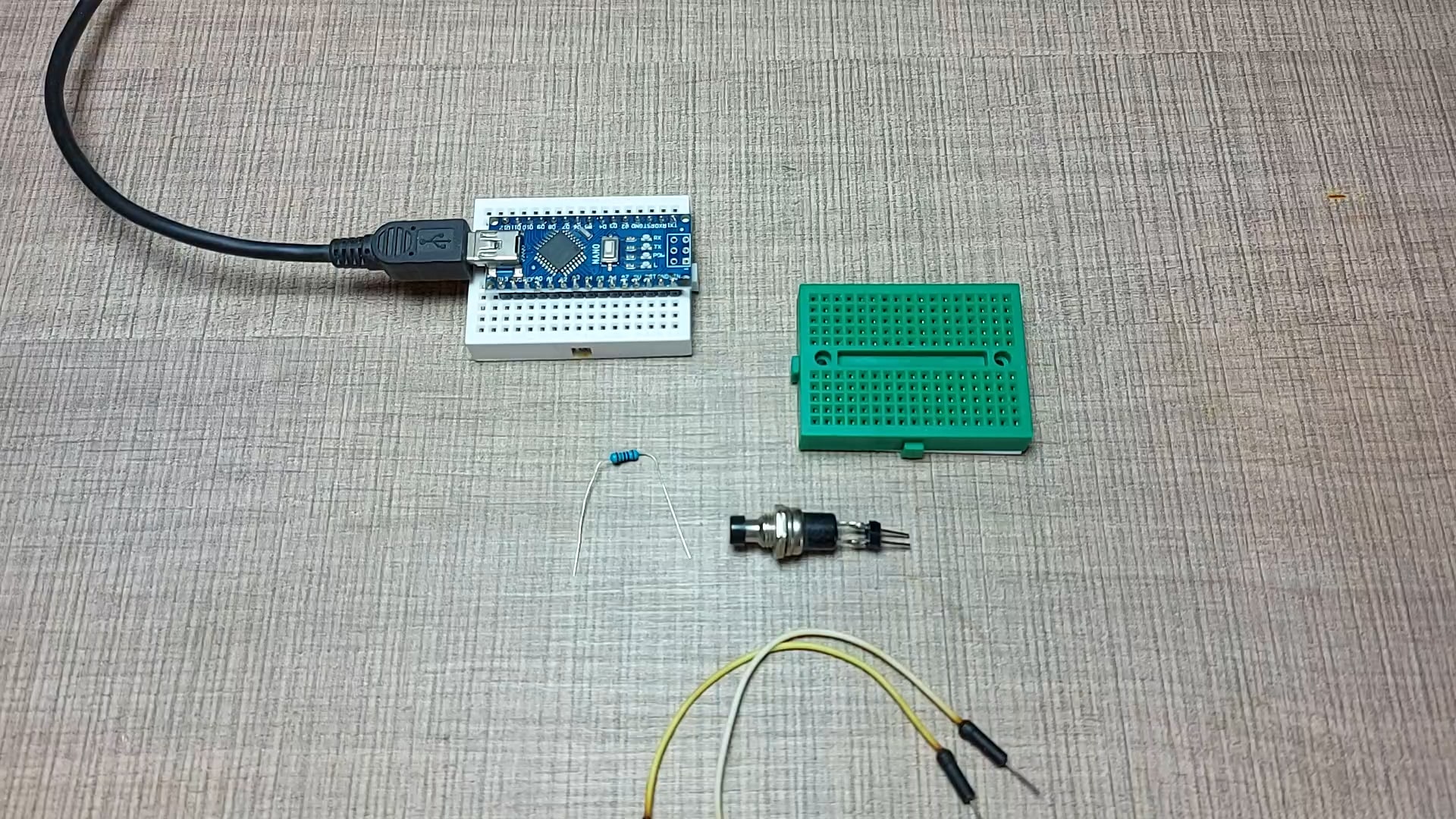
Required components
We can place the switch on the breadboard and connect one of its poles to 5V through the resistor and the other pole to ground. To register the button being pressed on the Arduino, I'll connect the pole that we have connected to the resistor, to a digital input pin. In my case, I'll use pin 2 but any other will work as well.
In this configuration, the Arduino will continually register the 5V coming through the resistor while the switch is not pressed but as soon as we press it, this pin will now be directly connected to ground and the Arduino will read 0V or a digital low.
Code
// digital pin 2 has a pushbutton attached to it. Give it a name:
int pushButton = 2;
int oldValue = 1;

// the setup routine runs once when you press reset:
void setup() {
  // initialize serial communication at 9600 bits per second:
  Serial.begin(9600);
  // make the pushbutton's pin an input:
  pinMode(pushButton, INPUT);
  oldValue = digitalRead(pushButton);
}

// the loop routine runs over and over again forever:
void loop() {
  // read the input pin:
  int buttonState = digitalRead(pushButton);
  if (buttonState != oldValue) {
    oldValue = buttonState;
    // print out the state of the button:
    Serial.println(buttonState);
  }
}
To run the entire example, we have a very simple code where at the beginning we define two variables, one for the pin that we have the switch connected to, and another one for keeping what I call, old value of the variable.
This old value variable will keep the previous state of the button, whether it is pressed or not pressed and we will print that value on every change. This will prevent the Arduino from printing the read value all the time but instead print the value just when it changes.
The old value is first saved in the setup function and in the loop section, we read the new value of the digital input pin and if that value is different from the current value we first update the old value to the current value and print out the current state.
To try it out we can now upload the code to the Arduino and we can open up the Serial Monitor to see the printed output.
Pressing the button now should print a 0 when pressed and a 1 once released. However, this is not always the case and we see multiple ones and zeros being printed with each press. This behavior greatly depends on the type and the quality of the switch that you have, and it is called bouncing.
Debouncing
Because of the mechanical properties of the switch, when it is pressed, two metal plates touch inside making the electrical connection. However this is not always ideal.
The plates can have small imperfections or just be elastic enough that for a very short amount of time, they can "bounce" back and briefly break the connection before touching again.
This causes the Arduino to detect this as another press and it triggers the writing of the state multiple times. If instead we were actually triggering something externally through the Arduino, then this might cause us some issues.
For us to be able to solve this bouncing issue of the switch, we need to introduce a small delay between the actual press and when that press is being detected by the Arduino.
Hardware debouncing
To solve it with hardware, we can add a capacitor to the circuit, across the switch contacts. This way, when the switch is not pressed, the capacitor will charge itself to the same voltage as the supply so when we press the switch, the capacitor will add a few milliseconds of higher voltage presented to the Arduino before it is discharged and registered as a press.
Hopefully, by then, the switch would have settled and it will no longer bounce so the change is only detected once per press and release.
Software debouncing
Another option for debouncing is to use software tricks to delay the reading of the switch value and this can be done in many ways.
In our current code, we can simply add a delay at the end of the sketch so the new value will be read, only after that delay has passed, completely skipping the bouncing of the switch that only lasts for several dozens of milliseconds.
// digital pin 2 has a pushbutton attached to it. Give it a name:
int pushButton = 2;
int oldValue = 1;

  // the setup routine runs once when you press reset:
  void setup() {
   // initialize serial communication at 9600 bits per second:
   Serial.begin(9600);
   // make the pushbutton's pin an input:
   pinMode(pushButton, INPUT);
   oldValue = digitalRead(pushButton);
  }

  // the loop routine runs over and over again forever:
  void loop() {
   // read the input pin:
   int buttonState = digitalRead(pushButton);
   if (buttonState != oldValue) {
    oldValue = buttonState;
    // print out the state of the button:
    Serial.println(buttonState);
   }
  delay(50); //added for stability
  }
The main thing to note here is that your Arduino is not doing anything while it waits so if you were to update something or read another sensor, you will have to wait for this delay to pass. Again, that entirely depends on your project and applications. Sometimes this delay is not important at all as in our case but sometimes it might be.
For such cases where you can't afford to wait in code, there is an example in the Arduino IDE in the Digital section, called Debounce.
I won't go into details on how it works but it does a great job of keeping the Arduino running and checking other instructions while waiting for the switch to settle.
Switches are such a simple device, and yet, they can be so complicated at times. By following along, I hope that you now have a solid understanding of switches, what the different acronyms mean, and how to choose the right one for your project.
I definitely didn't managed to cover all that there is to switches so I would love to hear your suggestions for what I missed in the comments below.
Also, don't forget to like and subscribe, share this video with anyone that is just starting with electronics, and keep making things.
I hope you enjoyed and I'll see you all in the next one.
Tools and materials used in the video:
- Arduino Nano - https://s.click.aliexpress.com/e/_A8ed0i
- Mini breadboard - https://s.click.aliexpress.com/e/_A1snIW
- Breadboard wires - https://s.click.aliexpress.com/e/_9vxQ0q
- Rocker Switch - https://s.click.aliexpress.com/e/_AcpVlG
- Limit Switch - https://s.click.aliexpress.com/e/_AqnJGi
- Tactile Push Button - https://s.click.aliexpress.com/e/_AZqTXu
- Momentary Switch - https://s.click.aliexpress.com/e/_AdnPG2
- Toggle Switch - https://s.click.aliexpress.com/e/_AOUULy
- Slide Switch - https://s.click.aliexpress.com/e/_At9D4E
- DIP Switch - https://s.click.aliexpress.com/e/_A54PbY
- Rotary Switch - https://s.click.aliexpress.com/e/_A3X0lo
- Assorted Resistors - https://s.click.aliexpress.com/e/_A1qzju
- Assorted Capacitors - https://s.click.aliexpress.com/e/_APQYuq
- Air Pressure switch - https://s.click.aliexpress.com/e/_A9aqxc