Today on my bench I have this cool little crystal ball that shoots lightning inside. It is one of those small plasma balls that runs on 5 volts through a USB cable, and it belongs to my nephew. The problem started when it was accidentally plugged into 12 volts instead of 5, since it uses a barrel jack that looks like many other power supplies. After that mistake, it completely stopped working.
Since it is supposed to run on a low voltage supply, feeding it 12 volts most likely damaged something inside. So in this repair attempt, I am going to open it up, take a look at the circuit, and try to figure out what failed and if I can bring it back to life.

PCBWay offers services for custom PCBs, PCBA, 3D printing, CNC machining, Injection molding, and more.
Check out their shared projects section to explore ideas for your next project or order any of the already created PCBs from tousands of creators!
Opening the Plasma Ball Base
To get inside, I flipped the plasma ball upside down and started removing the screws from the base. The first thing I checked was the battery compartment. Inside, I found four AAA batteries connected in series, which means the battery pack can provide up to 6 volts. There were no hidden screws in that section, so I continued removing the rest of the screws around the bottom cover.
Once all the screws were out, I carefully lifted the base. I made sure not to pull too hard because there are wires connected between the bottom and the top part of the globe. After opening it, I could finally see the small circuit board and the internal wiring, which gave me access to the parts that might have been damaged by the 12 volt mistake.
Taking a Look Inside the Circuit
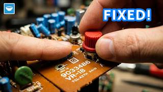
After opening the base, I carefully took out the small circuit board. It was much simpler than I expected. There were only a few components on it, along with a small transformer and a single transistor. On top of the high voltage section, I noticed a piece of steel wool placed under the globe. This is used to spread the high voltage evenly so the lightning effect appears on all sides of the glass.
The main parts I could see were a capacitor, a switch, a few resistors, and what looked like a high voltage transformer sealed in a black box. The transformer is responsible for stepping up the low voltage into a much higher voltage that creates the lightning inside the plasma ball. I also spotted a transistor labeled D882. Since the device was exposed to 12 volts instead of 5, this transistor immediately became my main suspect.
Identifying the Suspected Faulty Component
The first thing I focused on was the transistor marked D882. Since this plasma ball normally runs on 5 volts and was accidentally connected to 12 volts, I suspected that this part may have taken the hit. In circuits like this, the transistor is often used to drive the transformer by switching current on and off very quickly. If it fails, the transformer will not generate the high voltage needed for the lightning effect.
I looked up the part number and confirmed that the D882 is an NPN transistor. One important detail I noticed in the datasheet was its voltage rating. Knowing that the device was fed more than double its normal supply voltage, it made sense that this transistor could have shorted internally. There were not many other active components on the board, so this seemed like the most likely place to start troubleshooting.
Testing the Transistor
To check if the transistor was really bad, I placed the circuit board in my PCB holder so it would stay steady while I tested it. I grabbed my multimeter and first checked for continuity between the legs of the transistor. Right away, I saw a direct short between all three pins, which is not how a healthy transistor should behave.
Next, I switched the multimeter to diode test mode. A working NPN transistor should show a diode drop between the base and the other two legs in one direction only. Instead, I was getting readings that clearly showed something was wrong. The measurements did not behave like normal junctions, which confirmed my suspicion that the transistor had failed, most likely because of the 12 volt supply.
Finding a Replacement Transistor
Since the original D882 transistor was clearly damaged, I needed to find a replacement. I was not able to get the exact same part locally without waiting a long time for shipping, so I searched for something with very similar specifications. I managed to find a 2SD882 transistor, which has almost the same voltage and current ratings. The numbers were close enough that I felt confident it could work as a substitute in this simple circuit.
Before soldering anything, I carefully checked the datasheets for both transistors. Even if two parts have similar names, the pin layout can be different. I compared the base, collector, and emitter pins on the original SMD version and on the new transistor I had in hand. After confirming which leg was which, I planned how to bend and position the new transistor so it would match the connections on the board without causing clearance issues inside the case.
Replacing the Transistor
To remove the damaged transistor, I first added a small amount of fresh solder to its legs. This helps the heat spread more evenly and makes it easier to desolder. With my soldering iron, I carefully heated each pad and lifted the transistor off the board. After that, I cleaned up the pads to make sure they were smooth and ready for the new part.
Before installing the replacement transistor, I added a tiny bit of solder to its legs. Then I positioned it according to the pinout I confirmed earlier and soldered each leg in place. I took my time to make sure the joints were solid and not touching each other. Once it was secured, I tested it again with the multimeter in diode mode and saw normal readings this time, which gave me hope that the repair might actually work.
Reassemble and Test
Once I was satisfied with the soldering, I carefully placed the circuit board back into the base. I put the wire mesh back on top, made sure the switch lined up with its slot, and routed the wires so nothing would get pinched. At first, the new transistor was touching the plastic housing, so I had to bend the legs slightly to make it fit. During that adjustment, I accidentally lifted one of the pads from the board. I fixed it by shortening the leg and soldering it directly to the trace where it originally connected.
After putting the cover back on and tightening the screws, it was time for the moment of truth. I connected it to a 5 volt power source and switched it on. Unfortunately, there was no lightning effect inside the globe. I could see a tiny current draw, around one milliamp, but the circuit was not oscillating and the transformer was not generating high voltage. At that point, I suspected the black potted transformer module might also be damaged, which meant this repair attempt did not fully succeed.
Final Thoughts
Even though this repair didn’t bring the plasma ball back to life, it was still a valuable learning experience. I got to see how the circuit is built, identify the blown transistor, and practice desoldering and replacing a component carefully. Sometimes in electronics, a single mistake like applying too much voltage can cause multiple failures that are tricky to fix.
For anyone new to repairs, this is a good reminder to always double-check the voltage before plugging something in. Not every repair will work out, but exploring how things are built helps you understand circuits better. I’ll add this plasma ball to my “failed repairs” collection, but it’s a fun reminder that even failed attempts teach you a lot and prepare you for the next project.
Related Electronics Items
- Plasma Ball - https://s.click.aliexpress.com/e/_c3rIt1vp
- High Voltage Transformer - https://s.click.aliexpress.com/e/_c3lhDXyn
- Pulse Igniter - https://s.click.aliexpress.com/e/_c4TciZN1
- D882 Transistor - https://s.click.aliexpress.com/e/_c3syDXAT
- 2SD882 Transistor - https://s.click.aliexpress.com/e/_c3lo9iFh
- Tesla Coil Kit - https://s.click.aliexpress.com/e/_c45M2bPz
- Arduino Starter Kit - https://s.click.aliexpress.com/e/_c3wNHu3v
- Bench Power Supply - https://s.click.aliexpress.com/e/_c3gI3Q4b
- Soldering Station - https://s.click.aliexpress.com/e/_c4sPEieR