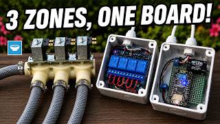
I’m working on a bigger electronics project, and I ran into a common problem: power waste. My project uses an ESP32 board along with several external sensors. The issue is that these sensors don’t need to be running all the time, but leaving them powered constantly drains the battery. I needed a way to switch them on only when the ESP32 is doing its job, and then completely cut their power when it goes to sleep.
To solve this, I built a simple electronic switch using a component called a P-channel MOSFET. This lets my ESP32 control a higher power circuit with its tiny 3.3-volt signal. The goal is simple: when the ESP32 wakes up, it flips the switch on to power the sensors. When it finishes its task and goes back to sleep, the switch turns everything off. This way, the sensors draw zero power for most of the time, which saves a huge amount of energy.
This video is sponsored by Altium Develop.
The Problem
The problem started with my ESP32 board going into sleep mode to save power. This is great for the board itself, but the sensors I have connected to it were still powered on, slowly draining the battery for no reason. They were just sitting there using power even though they weren't doing anything useful until the next time the ESP32 woke up.
I realized I needed a separate switch that could completely cut power to all the sensors whenever the main board was asleep. This switch had to be controlled by the ESP32 itself. It needed to turn on automatically when the ESP32 woke up and turn off just as automatically when the ESP32 went back to sleep.
Why P-Channel MOSFET
The reason I chose a P-channel MOSFET specifically comes down to how I need to switch the power. My digital sensors use a communication standard called RS485, and for them to work reliably, their ground connection must never be interrupted. They need to stay permanently connected to ground.
This means I can't switch the negative or ground wire to turn them on and off—that would break their connection. Instead, I have to switch the positive wire. This is called high-side switching. A P-channel MOSFET is perfect for this job because it's designed to sit on the positive side of the circuit and control the flow of power from there.
When the MOSFET is off, the positive voltage is blocked, but the sensors ground stays connected. When I turn the MOSFET on, it allows the positive voltage to flow to the sensors, powering them up, all while their ground remains stable. This setup keeps my sensors happy and ensures clean, stable communication every time the ESP32 wakes them up.
Circuit Explanation
The main component is a P-channel MOSFET, which acts like the main power switch for the sensors. It's a tiny chip that can handle the 12 volts my sensors need. Normally, this switch is off, so no power gets through. To turn it on, I need to pull its gate pin to ground.
But there's a catch. The ESP32 only provides 3.3 volts on its signal pins, which isn't enough to directly control the MOSFET's gate in the right way. So, I added a small transistor (2N2222) as a helper. When the ESP32 sends a "high" signal, it turns on the transistor. This transistor then connects the MOSFET's gate to ground, which flips the main power switch on.
A couple of resistors are there to make sure everything is in a known state. One resistor pulls the MOSFET's gate up to keep it off when the transistor is off. Another resistor protects the transistor's base. It's a simple team: the ESP32 tells the transistor, the transistor controls the MOSFET, and the MOSFET switches the high power for the sensors.
The Altium Develop project is available for download to my Patrons.
Building the Prototype
I started building on a perfboard, which is a board with a grid of holes for prototyping. First, I soldered down two sets of terminal blocks. These are the connectors where the 12-volt power comes in and where the sensor wires will later plug in. I made sure to keep the positive and negative terminals well separated to avoid any accidental shorts once everything is in an enclosure.
Next, I placed the MOSFET and the transistor. I bent their legs slightly to hold them in place and soldered them down, using the legs themselves to make some of the connections to the power and ground rails. After that came the resistors. I used two 10k ohm resistors as pull-ups and one 1k ohm resistor to connect the ESP32's signal pin to the transistor's base. I bent the resistor leads over to bridge the gaps between components and soldered them.
Finally, I used some spare copper wire to connect all the ground points together and to link the positive terminals. During my first test, I realized I had the drain and source pins of the MOSFET swapped, which is exactly why we build prototypes! I carefully swapped the connections, and that fixed it. This kind of mistake is much cheaper to fix on a homemade test board than on a professionally manufactured PCB.
Conclusion and Next Steps
Now that my prototype is working perfectly, I'm ready to make it permanent. Building circuits by hand on a perfboard is great for testing, but it takes time and isn't very sturdy for multiple copies. Since I need several of these switches for my project, I'll turn this design into a proper printed circuit board, or PCB.
I'll use the fixed layout from my design software to order the boards from PCBWay. This way, every board will be identical, compact, and reliable. I can just solder the components onto the pre-made pads and traces, which is much faster and cleaner than hand-wiring each one.
Once the new PCBs arrive, I'll assemble them and integrate each switch into my larger project. This little circuit solves the power waste problem neatly, letting my ESP32 and sensors run for much longer on a battery.
This project shows how a few simple components can make a big difference in saving power. If you enjoyed seeing this build and want to learn more, consider subscribing to my YouTube channel. I share new projects and tutorials there regularly, and I'd love to have you join the community.
Thanks for reading, and I hope to see you in the next video.