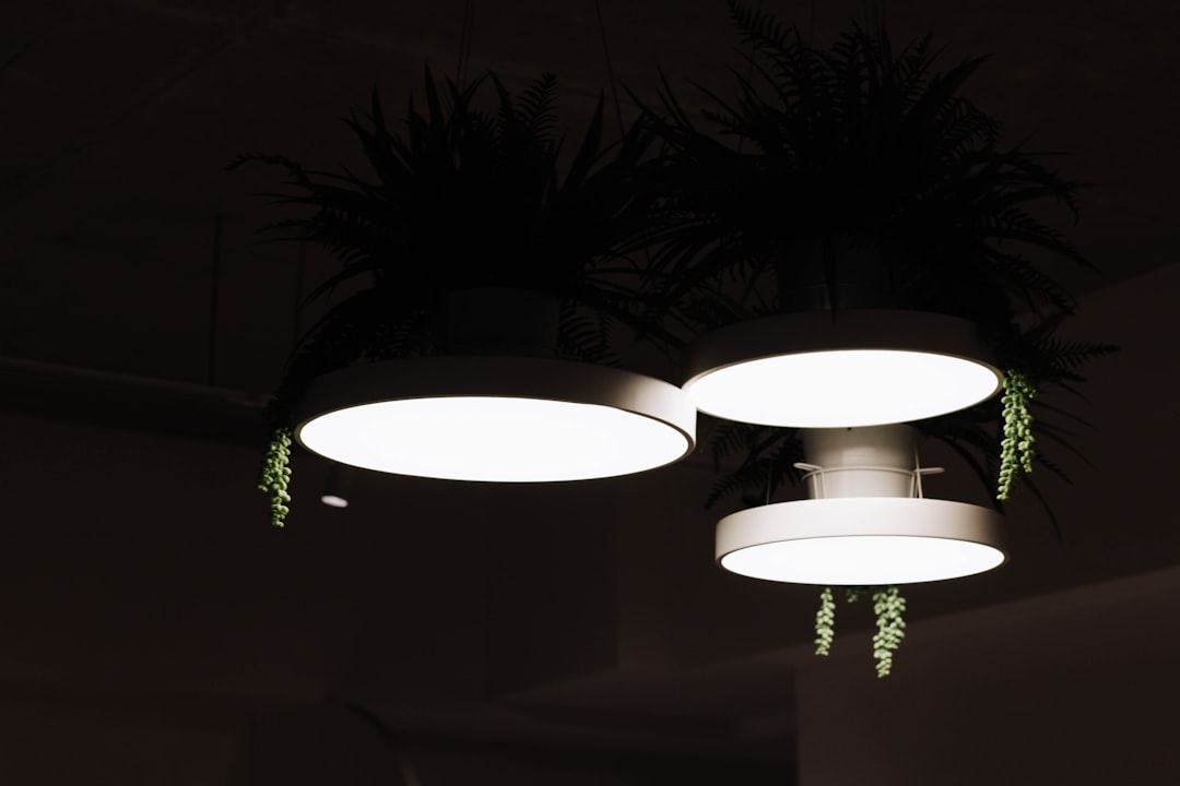
Last week, these three Lambario branded 18W LED panels failed just a few days apart from each other.
This was suspicious, as the panels were only about 9-10 months old, and were not used much as they were installed in a hallway, so I set to open them up and investigate the fault. Below is a video of the process if that is your thing.
In the end, I repaired all three of them and even went a step further to modify their driver boards so that I could lower their current consumption by ~30%, without any noticeable difference in the light output.
These lights operate on mains voltage that can easily kill you if you are not careful! Attempting any steps and actions shown here is at your own risk!
Investigating the LED driver
The LED driver board is housed in a plastic box that can be easily opened with a flathead screwdriver. Once the bottom cover is removed, the entire circuit can be removed and taken outside for investigation.
Keep in mind that these drivers usually have big capacitors that can hold charge for quite a long time and that they can zap you if you are not careful. Before handling the driver circuit, make sure that you discharge them by bridging the contacts with the screwdriver.

On initial investigation, the driver board looked OK, without any visible burn marks and all components looked good. There were no bulging capacitors as I faced on previous repairs and since the lights failed deterministically, I was quite confident that the issue was not on the driver's side.
Opening the LED panels
The LED panel construction is done so that the panel is held in place with dents made in the outer metal ring. During construction, these are placed inside and a machine presses from the outside to create these dents, securing the light inside.
To open them up, you need to gently press on the glass from the outside, while twisting the outer ring outwards to create enough clearance so the panel can move up and past the dents.
Once removed, we can separate the back plate from the rest of the glass and diffusers, so we can take a look at the LED strip inside that is glued on the backing plate.
Testing out the LEDs
Different lights have different construction methods so this part might be different for you. In my case, I was able to use my multimeter to test out the LEDs in diode mode.
The diode mode applies a small voltage across the LED, and in most cases with panel lights, this is enough to make the individual LED segments light up when tested. I was able to identify that the strip was constructed of 45 series of two parallel LEDs, making a total of 90 LEDs.
Testing out each section, I identified a pair that was not lighting up and there was no response on them from the multimeter. This indicates that those LEDs have failed open-circuit, meaning that they were not conducting any electricity and caused a break in the circuit.
In the first panel, these were not visible immediately until I tested them with the multimeter, but later on, when I checked the other two panels, they had really visible and easily identifiable black burn marks in the center of the LED that did not work.
Repairing the LED Strip
Since the strip is connecting these LEDs in series, the easiest way how we can fix it is to remove the burnt LEDs and just bridge the circuit with a piece of wire. I know that this might sound strange, but since the LED driver is created to provide a constant current to the strip, it will automatically adjust the output voltage so that it lights the panel in the same way.
To remove the bad LEDs, I used my soldering iron at 450 degrees Celsius, to melt away the LEDs. Since the strip is glued to a metal backing, extra heat is needed to melt the solder.
Once the LEDs are removed, we can bridge any of the two with a small wire, so we can establish the current path for the rest of the LEDs.
Testing the repair
Now that the panel was hopefully repaired, I wanted to test it out and for that, I used my Dim Bulb Tester. The Dim Bulb Tester is a device that I made myself, that uses a 100W incandescent light bulb to connect it in series with the device under test. This is a technique used in audio equipment repair, where the incandescent light acts as a current limiter for the tested device so even if the tested device has a short circuit inside, the worst that can happen is that the light will glow and there will be no explosions or further damage caused on the tested device.
So when I connected the panel, to my delight, it started glowing and was back in operation.
I repeated the repair procedure for all three panels and all of them had the same fault and were fixed in the same way.
Reducing the driver's current
With the panels repaired, I noticed that some LEDs were flickering when I tested them, so potentially, those can also fail soon. I guess what they failed in the first place is that they were pushed too hard to provide the 18W output, so they were running quite hot.
An option to mitigate this is to reduce the current on the LEDs and for that, we need to figure out the driver circuit and to figure out how we can modify it. By reducing the current, each LED will need to dissipate a bit less energy so it will run cooler, and potentially it will run for a much longer time.
The LED driver uses a chip marked as 1FYL9T2CC, but I was unable to find any datasheet for it. However, by following the circuit and comparing it to other drivers, I was able to figure out that there is a resistor from pin 7 connected to ground that is used to set the output current.
Out of the box, the repaired lights were using a bit over 17W so that was our starting consumption.
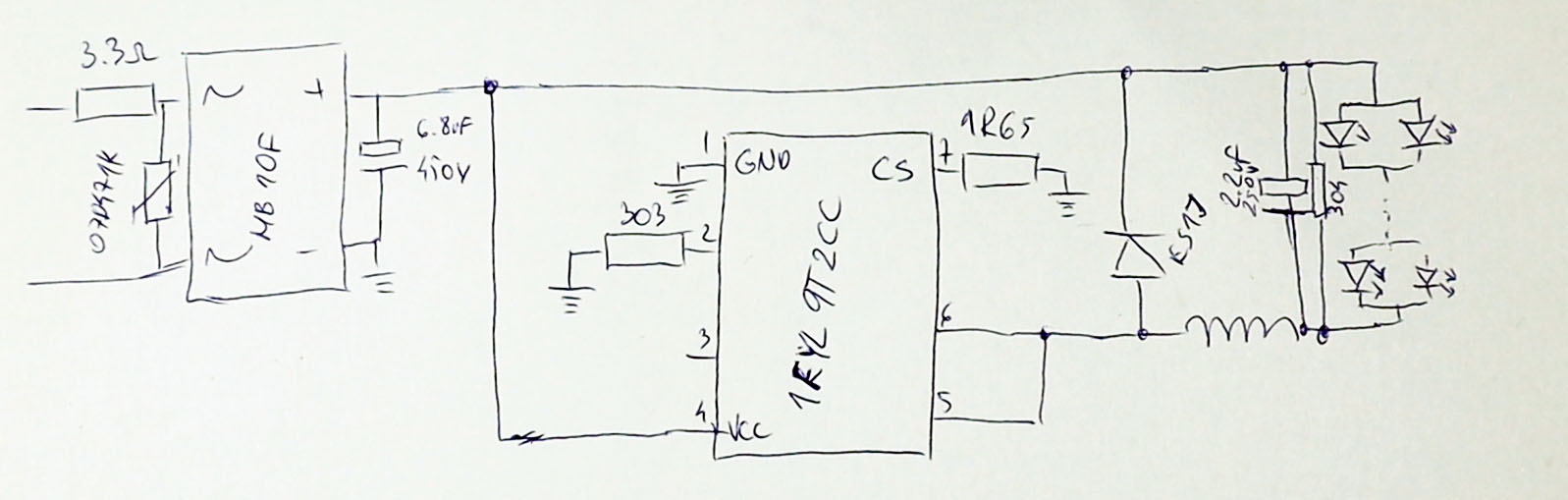
LED Driver circuit for the 1FYL9T2CC chip. The 1.65 Ohm resistor is used for current sensing.
Since I did not have a datasheet for the chip, I decided to experiment and try to first double the resistance to see what effect that would have on the output.
Looking at my parts drawer, I did not find a 3 Ohm resistor, so I first used two 8 Ohm resistors in parallel so I could get to 4 Ohms which I thought was close enough. I soldered those in place of the 1.65 Ohm resistor, but when I tried to run the light, there was a brief power draw from the panel that quickly went down to 0 and there was no output from the light.
Since this was probably too much, I then tried to use the existing SMD 1.65 Ohm resistor and add 1 Ohm resistor to it. On my first attempt at soldering this, I almost succeeded, but when I tried to push on the through-hole resistor I added, I accidentally broke the SMD resistor 🤦♂️. I learned my lesson, so on the second driver, I soldered the resistor and I did not move it at all so I could test the light.
This time, the light did turn on and the power meter was showing only 10W so with just that 1 Ohm, we've reduced the power consumption almost by half while still providing decent light output. The panel was a bit dimmer than before but still very usable.
However, when I turned off the panel, the light flickered a few times and this was happening on every power off. I'm guessing that the capacitor held enough charge to trick the LED driver chip into thinking that it needed to start the circuit again and this repeated several times until there was no more power in the capacitor.
Since I did not want that, I finally tried an option where I connected two of the 1 Ohm resistors in series, and with them, the light was running normally, there was no visible reduction in the output light and the panel was using 14W.
This seemed like the best option so I modified all panels this way and called it done.
Final verdict and next steps
With the panels running, I must say that I enjoyed this repair. It looks like the LEDs are being pushed too much so the lights are not that durable (planned obsolescence ?!?) but there seems to be an easy way for tinkerers to modify them.
I'll use the repaired panels as spares and I definitely won't install them in hard-to-reach places as I'm suspecting the flickering LEDs to fail soon. Knowing the panel and driver construction, we can repair them once again by just bridging over them so we can squeeze a bit more life out of the rest of the LEDs.
If you liked this article, I will recommend that you subscribe to my YouTube channel where I have a lot more repairs and electronics projects for you to check out.
Below is a list of tools and materials I used in the video that you can check out. They are affiliate links so by buying through them, you are supporting my work at no extra cost to you. Any support is more than welcome.
If you have any questions or suggestions, feel free to use the comments form below to continue the discussion and I will see you all in the next one.
- Soldering Rework Station - https://s.click.aliexpress.com/e/_opbD1ac
- Multimeter - https://s.click.aliexpress.com/e/_olaaKg4
- Soldering Iron with tools - https://s.click.aliexpress.com/e/_EzO2Ppj
- Helping hand for soldering - https://s.click.aliexpress.com/e/_oBVdwbi
- Fumes extractor - https://s.click.aliexpress.com/e/_oB47YEu
- Screwdriver Set - https://s.click.aliexpress.com/e/_msUOArM
- Tweezers - https://s.click.aliexpress.com/e/_omYbydQ
- SMD LEDs - https://s.click.aliexpress.com/e/_mMKLeTy